
I had a remote controlled power plug (Figure 1) purchased from Home Depot (or Amazon, cannot remember anymore) whose remote was malfunctioning. The On button would work but the Off button did not. I saw this Hak5 video on the Yardstick One and realized I could try doing the same with the YardStick One I had purchased a few years ago, but never used. If you love watching videos instead of reading blogs, the Hak5 video linked earlier is good enough. However, if you prefer reading a blog instead, this post is for you.
Since this post could be relatively long, the Table of Contents below can allow the reader to skip to the appropriate section of interest.
TABLE OF CONTENTS
- 1. Pre-requisites
- 2. Setup Software
- 3. Finding Information
- 4. Sniffing the Radio Waves
- 5. Decoding the On-Off Messages
- 6. Transmitting the On-Off Messages
Pre-requisites
This post requires you to run this on any supported Linux distribution. I used the latest Kali Linux for testing this out, along with the Elonics 4000 RTL-SDR dongle and the Yardstick One.
- Operating System: Kali Linux or equivalent
- Elonics 4000 RTL-SDR dongle (Figure 2) or equivalent SDR hardware such as HackRF, Ettus USRP, BladeRF etc.
- Yardstick One (Figure 3)
- Antenna for Yardstick One. ANT500 is quite expensive, so I got a clone from Amazon for $8, as of July 2021.
- Remote controlled power plug from Home Depot or Amazon (Figure 1)
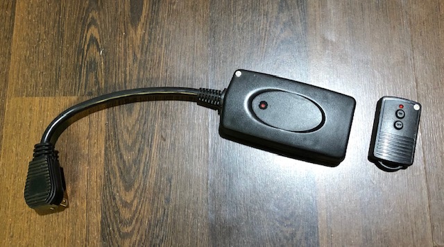 Figure 1. Remote controlled power plug
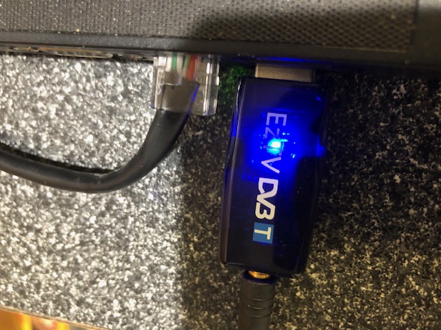 Figure 2. RTL-SDR dongle
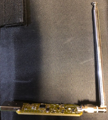 Figure 3. Yardstick One with Antenna
Setup Software
On the Linux system, you need to run the following command to install the required software to accomplish this procedure.
$ sudo apt-get -y install gqrx audacity rtl-sdr rfcat
I also setup udev rules for rfcat to be able to run without root using the 20-rfcat.rules file, and
rebooted the system before use. The user has to be added to the dialout group to take advantage of the udev rules.
NOTE: If you do not want to do this you will need to run rfcat under sudo.
$ sudo cp 20-rfcat.rules /etc/udev/rules.d/
$ sudo adduser $USER dialout
$ sudo reboot
Finding Information
Step 1: Find the radio frequency receive/transmit details of the remote controlled power plug. For that you look at the FCC ID printed on the transmitter, which in our case is the remote (Figure 4) and it is PAGTR-009-1B.
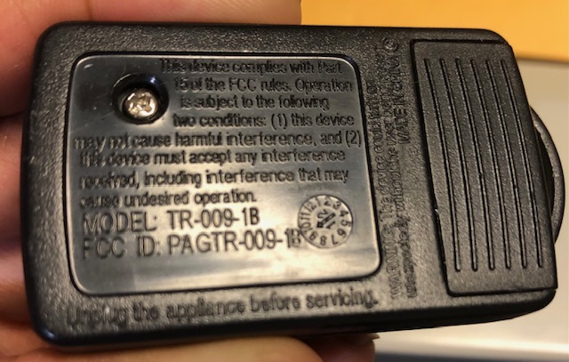 Figure 4. FCC ID printed on remote
Step 2: Go to fcc.io and type in the FCC ID and hit Search which will take you to this page as seen in Figure 5.
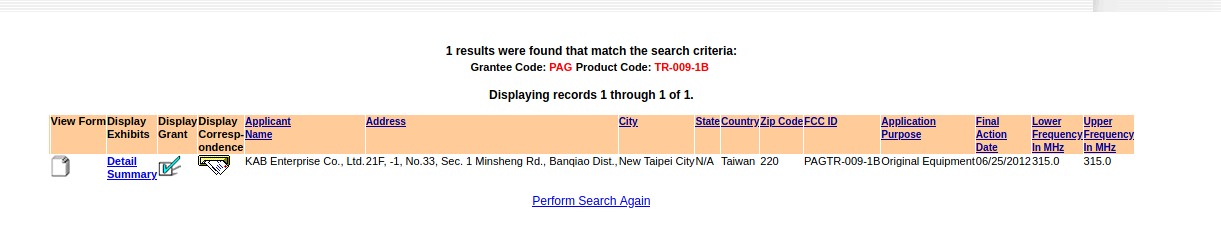 Figure 5. Search results on the FCC ID
Step 3: In the above image you can see that the remote transmits on the 315MHz band. Click on the link that says Detail in the search results. It will bring you to the list of documents filed by the manufacturer of the remote controlled power plug, as seen in Figure 6.
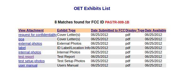 Figure 6. Detailed documents for the remote control
Step 4: Click on the document titled test report and open the PDF. Scroll to the section 2 and you can see the details of the exact frequency at which the remote transmits, which is 314.902 MHz, as pointed by the
red arrow in Figure 7. The remote also uses ASK or Amplitude Shift Keying to send data over the radio waves. Since the purpose of the remote is to just send on and off digital signals, we can also assume it uses the OOK or On-Off Keying form of ASK.
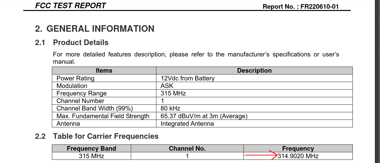 Figure 7. Test report screenshot showing frequency information
Now let’s sniff the radio waves.
Sniffing the Radio Waves
Sniffing is accomplished using the RTL-SDR dongle and the gqrx program.
Step 1: Make sure it is plugged into your USB port first and that Linux can detect it. You should be able to see it listed, if you run the lsusb command, as seen below. The line that says RTL2838 denotes that the dongle has been successfully
detected.
$ lsusb
Bus 002 Device 002: ID 8087:0024 Intel Corp. Integrated Rate Matching Hub
Bus 002 Device 001: ID 1d6b:0002 Linux Foundation 2.0 root hub
Bus 001 Device 004: ID 04f2:b221 Chicony Electronics Co., Ltd integrated camera
Bus 001 Device 005: ID 0bda:2838 Realtek Semiconductor Corp. RTL2838 DVB-T
Bus 001 Device 002: ID 8087:0024 Intel Corp. Integrated Rate Matching Hub
Bus 001 Device 001: ID 1d6b:0002 Linux Foundation 2.0 root hub
Step 2: Start the program gqrx by either using the search bar in the menu on the Kali Linux desktop, or by typing the command gqrx in the terminal. This is not a tutorial on gqrx, so I will assume you already know how to use it.
Step 3: Verify that the gqrx is able to see the RTL-SDR dongle in its settings as shown in Figure 8.
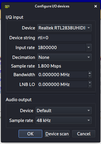 Figure 8.
 gqrx settings for RTL-SDR
Step 3: Set the frequency to 314.902MHz in the gqrx UI and hit the ► (or play) button to start listening at that frequency. Note to record and save the radio waves in an audio .wav file format you must hit the Rec button at the bottom of the screen in gqrx, as shown circled in red in Figure 9.
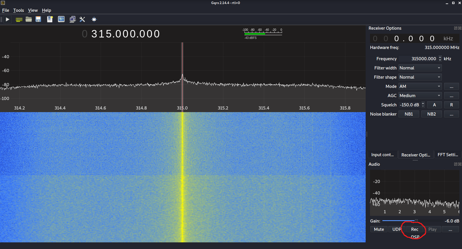 Figure 9. Set the frequency in
 gqrx
Step 4: Hit the ► button and the Rec button to start recording to a .wav file automatically.
Step 5: Now press the remote control On key a few times, or hold it till you see a lot of waveforms on the screen. If your system has a speaker, you will also be able to hear it.
With some minor trial and error, you can align the waveform’s white line as seen in the lower red circle in Figure 10, with the red axis/indicator line as seen in the upper red circle in Figure 10. You have to be as close as possible so that when the waveform is saved, the exact data bits get saved correctly.
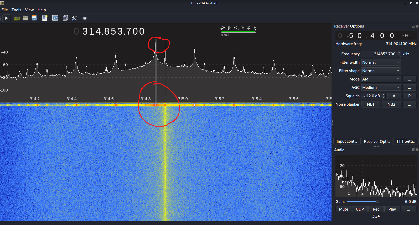 Figure 10. Waveform seen in yellow after pressing the On button continuously on the remote
Step 6: Now repeat the same procedure for the remote control’s Off key a few times and save the .wav file.
I provide saved copies of my On button press waveform file and Off button press waveform file for you to download and refer, if necessary.
NOTE: In my case since the remote control was not functioning properly, I opened it up and then pressed the switches that were on the circuit board directly and it sworked (Figure 11). As you can see, the remote control has a pretty simple design.
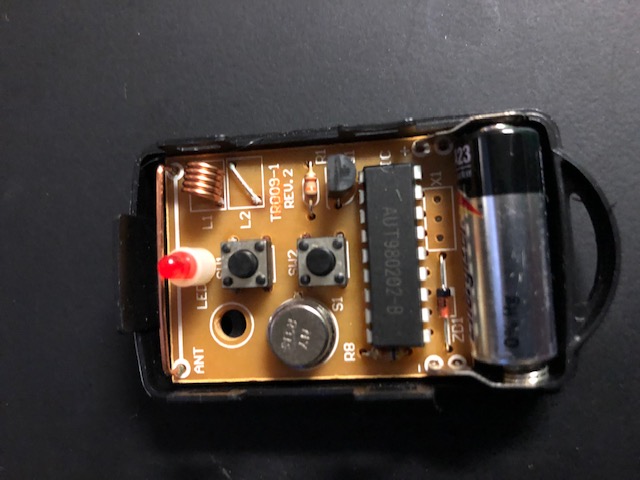 Figure 11. Remote control internal circuit board
Step 7: Now that we have saved the wave files, let’s use audacity to view and decode them.
Decoding the On-Off Messages
Step 1: Start audacity by typing audacity on the command line or using the menu search bar in the UI.
Step 2: Open one of the .wav files. In Figure 12 below, I am using the On button press waveform file.
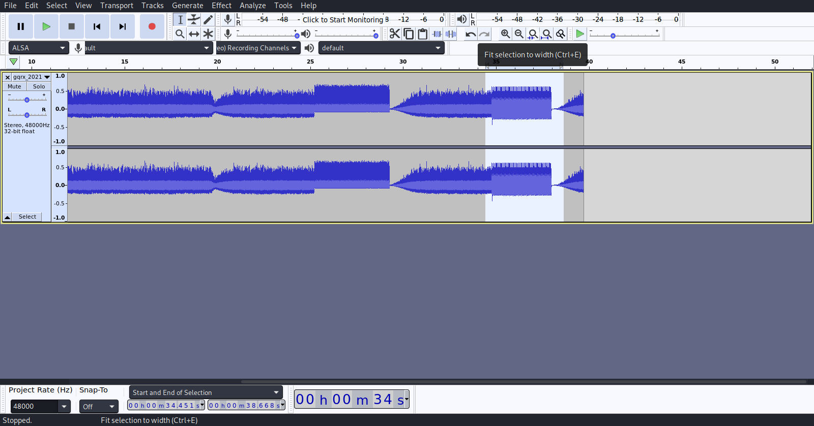 Figure 12. On button press waveform file
Step 3: Zoom in to locate the repetitive signal of the button press you are decoding. You can see the periodic signal in the waveform as seen in Figure 13.
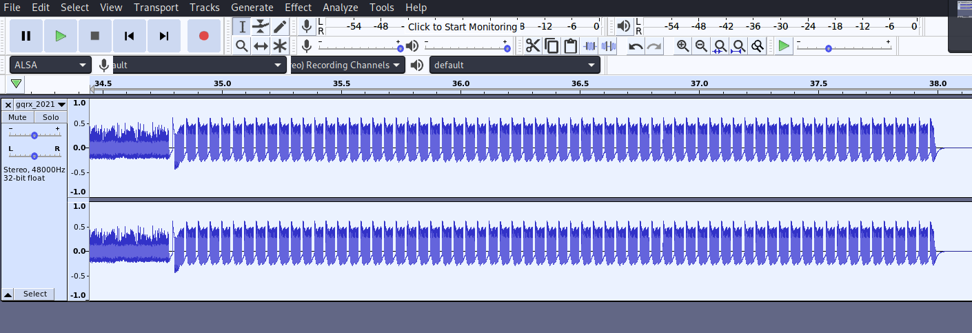 Figure 13. Locate the repetitive signal
Step 4: Further zoom in to see the actual bytes of the signal as seen in Figure 14. You can see the peaks and troughs in the signal representing the 0s and 1s in the signal byte-stream.
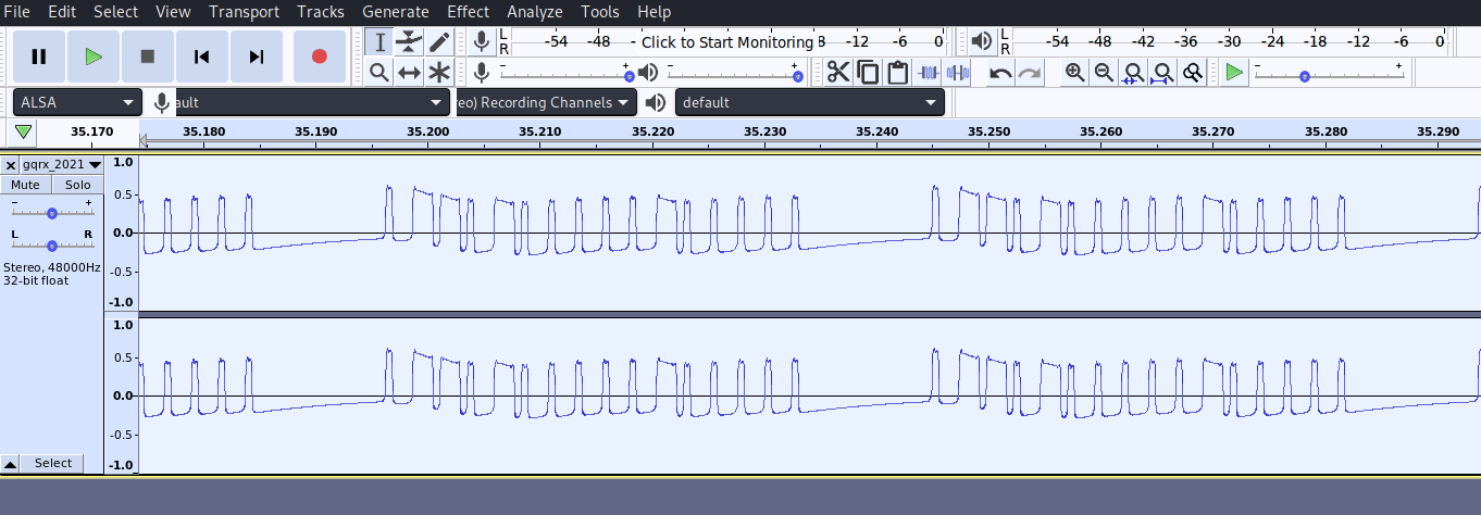 Figure 14. Further zoom in to see the actual signal
NOTE: Based on the waveform we can definitely say that the remote control is using OOK as guessed in the previous section.
Step 5: Let us calculate the approximate baud rate to determine how long a 1 signal lasts. In our case it lasts 0.0006 seconds, as seen in Figure 15. We subtract 2.6954 and 2.69548 to get that value. If you want to be more accurate, you can probably assume it to be 0.00056 seconds but our approximation is good
enough. This gives us a baud rate of 1 / 0.00056 which is a baud rate of 1785, and the closest approximation to that is 1800 baud.
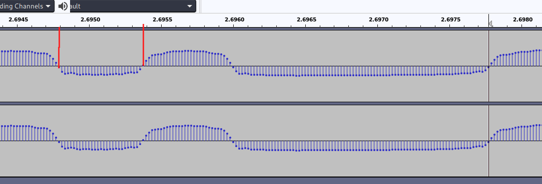 Figure 15. Calculate the baud rate
Step 6: Decode the signal by using the 0.0006 measurement to count the bytes in the peaks and troughs and write it down. Figure 16 shows the On switch press signal which decodes to 1000 1110 1110 1000 1110 1000 1000 1000 1000 1000 1110 1000 1000 1000 1000 1000 in binary or 0x8ee8e88888e88888 in
hexadecimal. You can also see that there is some dead space between the signals and that can be interpreted as 0 bytes or NULL.
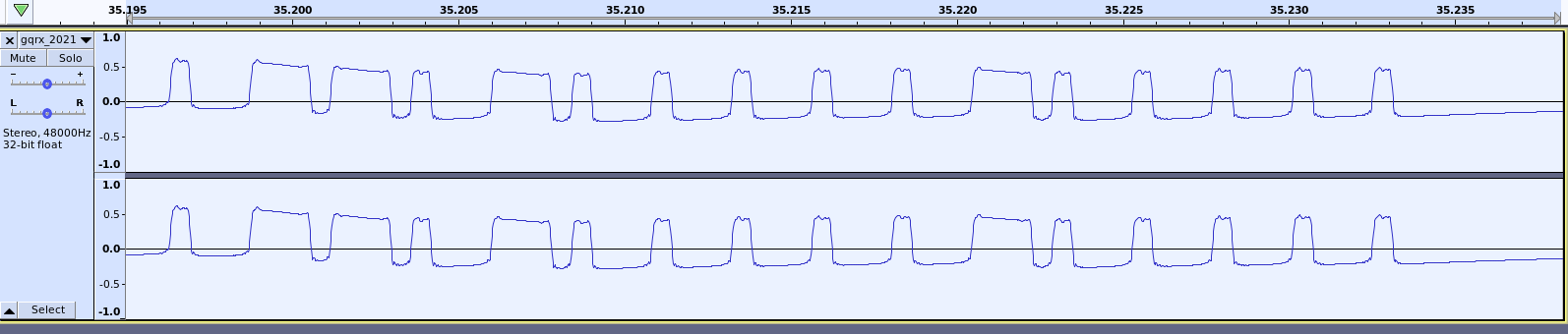 Figure 16. On Signal
Similarly, the Off signal in Figure 17 decodes to 1000 1110 1110 1000 1110 1000 1000 1000 1000 1000 1000 1110 1000 1000 1000 1000 in binary or 0x8ee8e888888e8888 in hexadecimal. Note that these signals look quite similar, but are different.
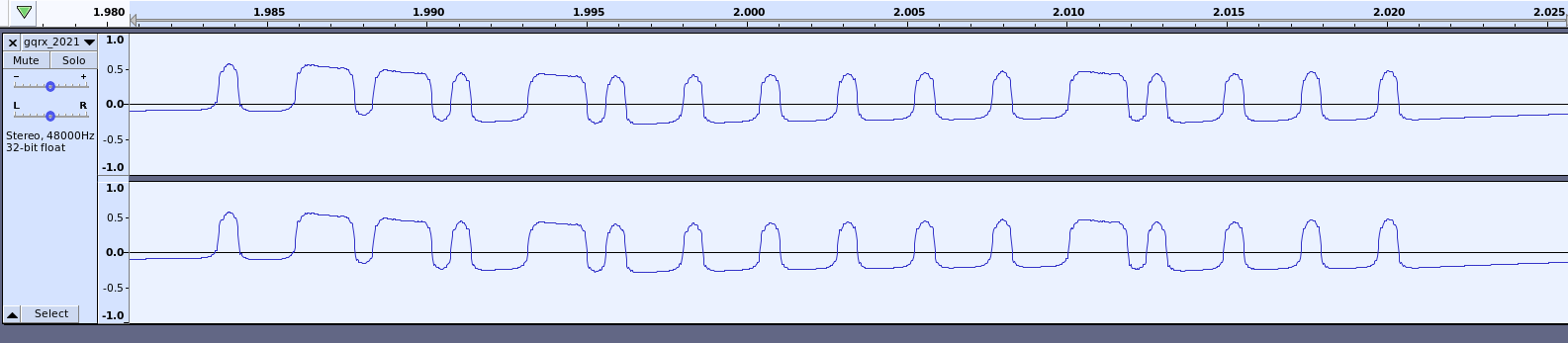 Figure 17. Off Signal
Now that we have decoded the signals, let us try to transmit them with the Yardstick One.
Transmitting the On-Off Messages
Step 1: First plug in the Yardstick One into the computer’s USB port as shown in Figure 18. When you run lsusb it will show a string with OpenMoko in the description, and that is the Yardstick One.
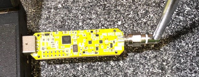 Figure 18. Yardstick One with Antenna plugged into the computer
Step 2: Start rfcat as below. If you did not install the udev rules outlined in the Setup Software section, then run it under sudo.
$ rfcat -r
For more details on the rfcat commadline API, read the Github code or this article by GiamMa-based SDR Researchers, which I found incredibly helpful to understand the API. This article
describes each API function that we will be using in the next step, so I will not be reproducing the description here.
Step 3: Once inside the rfcat interpreter, run the following commands. The explanation of each command is in the comments. rfcat uses Python syntax, since technically it is an iPython interpreter.
## set the frequency from the FCC ID document, which is 314.902 MHz
rfcat> d.setFreq(314902000)

## set the modulation type to be ASK (from the FCC sheet) and OOK from the waveform file
rfcat> d.setMdmModulation(MOD_ASK_OOK)

## set the baud/data rate to be 1800
rfcat> d.setMdmDRate(1800)

## set packet size to 16 bytes
rfcat> d.makePktFLEN(16)

## transmit the ON signal 8 times. You can transmit any number > 1 to make sure it works
## Recall that the signal itself needs to be followed by NULL bytes to handle the dead space in the waveform
rfcat> d.RFxmit(b"\x8e\xe8\xe8\x88\x88\xe8\x88\x88\x00\x00\x00\x00\x00\x00\x00\x00" * 8)

## transmit the OFF signal 8 times.
rfcat> d.RFxmit(b"\x8e\xe8\xe8\x88\x88\x8e\x88\x88\x00\x00\x00\x00\x00\x00\x00\x00" * 8)
Step 4: Every time you transmit the On or Off signals, you should see the power plug respond by its internal LED turning on or off. I connected a table fan to the power plug to see if it turned on or off when I gave the correct commands, and it did.
This project was a success and I was able to replicate the work done in the Hak5 video. Hope it helps you understand how to go about sniffing and decoding simple remote control signals that work on the 315MHz band, by using the Yardstick One.
 Donate BITCOIN to 19hrWWw1dPvBE1wVPfCnH8LqnUwsT3NsHW.